
Ideal for Christmas Lights or a Music Light Show.
Worlds most sophisticated Color
Organ.
For info:
circuits(at)jspayne.com
Circuit Features:
8 Modes of operation.
Input isolation to prevent ground loop noise
Micro processor controlled (ATMEGA)
Frequency selection dial
Gain Control
Current Limit/Overload Protection.
1500 Watt Outputs (non concurrent).
High/Mid/Low Separation Circuit
Input Level Averaging.
Analog Circuit
The audio signal enters through the isolation transformer. The isolation transformer (xfmr2) prevents ground loop noise from affecting the audio source. R14 is used to reduce the input sensitivity. The next 3 op amps separate the audio into low, medium, and high frequency. These signals are then “rectified” (negative) and filtered before being connected to the microprocessor's A/D inputs. R22 is used to select low/mid or high frequencies and then that signal is fed into another A/D input of the microprocessor.
Microprocessor Circuit

The ATMEGA processor is used to gather the analog input, process it and then it is used to output a signal to the three opto isolators. The opto isolators turn on and off the AC power to the lights being controlled. Each analog input is processed by obtaining a moving average and then when the input exceeds (or is lower than) the moving average by a predetermined value, an action is taken. The action may be turning on an output, turning off an output, rotating a pattern on the outputs... In addition, one opto isolator is used to monitor the current used by the connected lights. When the OL current signal is detected all outputs are turned off. SW1 is used to select the mode of operation.
AC Power Circuit
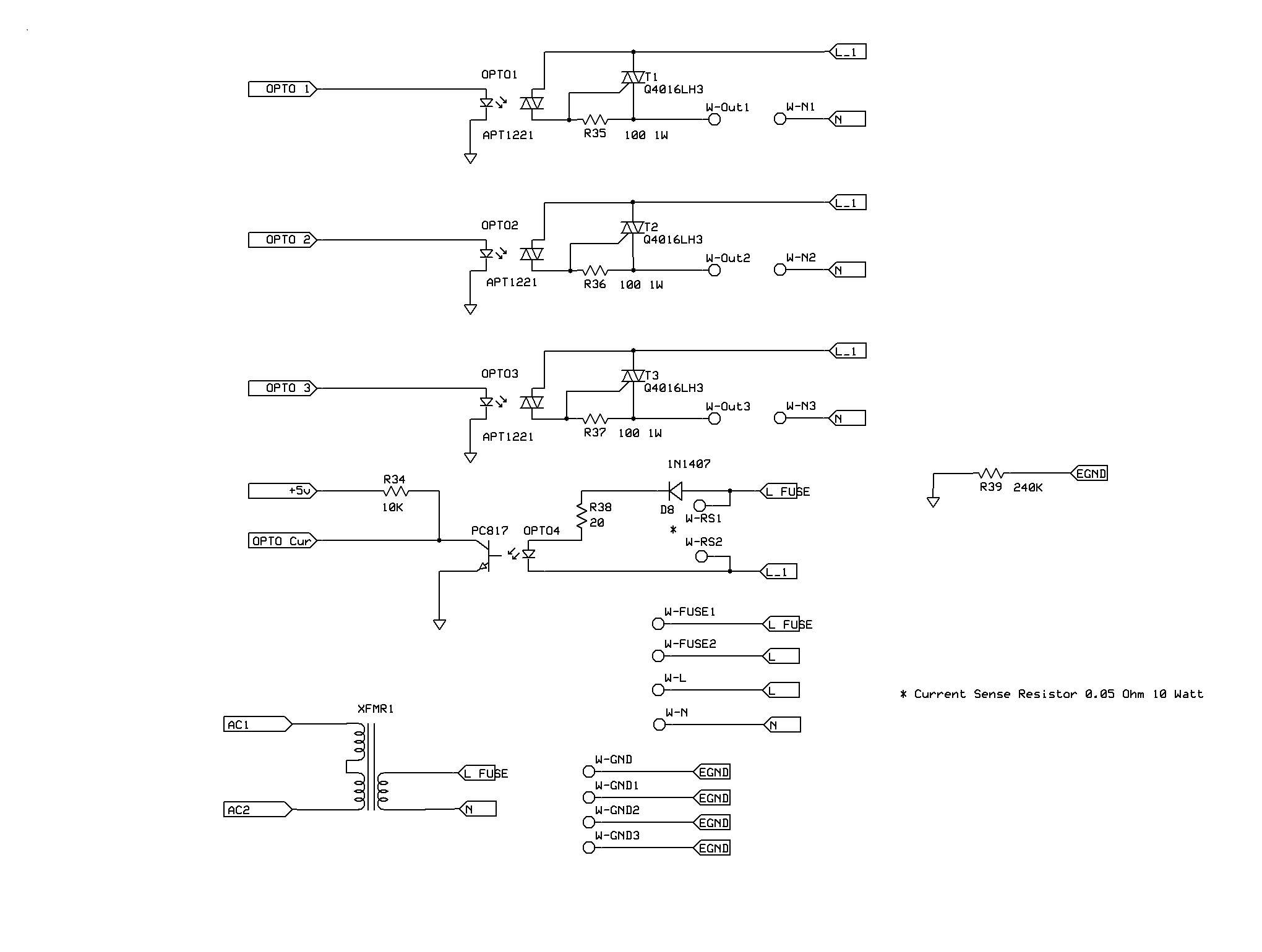
In the AC power circuit triacs are use to turn on and off the outputs. RS1 and RS2 are connected to a current sense resistor of 0.05 ohm 10w. 0.05 ohm gives a current limit of about 13 amps. Note: a fuse of the appropriate size for the line cord used should be employed.
Power Supply Circuit

The
power supply circuit is pretty much straight forward. The only
thing that should be noted is that for the analog processing
circuit, +5v is used as the common(or center), common is used as a
-V and +V is just +V.