Serial and Parallel cable schematics and wiring diagrams.

Home Page

Use the I/O ActiveX control for serial and parallel communication.  ASCII Code Table

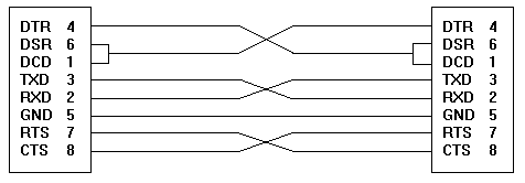
9 PIN to 9 PIN Serial Cable

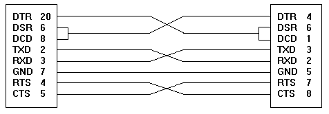
25 PIN to 9 PIN Serial Cable
 

Parallel Printer Connector Db-25
DB-25 PIN (Female) SIGNAL
DB-25 MALE CONN DB-25 FEMALE CONN
1 ------------------------------- > STROBE *
2 ------------------------------- > DATA 0
3 ------------------------------- > DATA 1
4 ------------------------------- > DATA 2
5 ------------------------------- > DATA 3
6 ------------------------------- > DATA 4
7 ------------------------------- > DATA 5
8 ------------------------------- > DATA 6
9 ------------------------------- > DATA 7
10< ------------------------------ ACK *
11< ------------------------------ BUSY
12< ------------------------------ PAPER END
13 ------------------------------ SLCT (select)
14 ------------------------------ >AUTOFEED *
15< ------------------------------ ERROR *
16 --------------------------->INITIALIZE PRINTER *
17 ------------------------------- SLCTIN (select in)
18 thru 25 ----------------------- GND
Note!! * denotes an active low signal.
 
Db-25 Parallel Loopback Connector Wiring
1 to 13 Strobe to select
10 to 16 ACK to INIT
11 to 17 BUSY to SLCTIN
12 to 20 PAPER END to GND
 
Rs-232 Serial (Com) Pc Port Connector Db-9
DB-9 PIN (Male) FUNCTION ABBREVIATION
1 --------------------------- Data Carrier Detect CD or DCD
2 ------------------------------ Receive Data RD or RX
3 ---------------------------- Transmitted Data TX or TD
4 ---------------------------- Data Terminal Ready DTR
5 ------------------------------ Signal Ground GND
6 ------------------------------ Data Set Ready DSR
7 ------------------------------ Request To Send RTS
8 ------------------------------ Clear To Send CTS
9 ------------------------------ Ring Indicator RI
Transmitted and receive data are referenced from the data device and
not the modem.
 
Rs-232 Serial (Com) Pc Port Connector Db-25
DB-25 PIN (Male) FUNCTION ABBREVIATION
1 ---------------------------- Chassis/Frame Ground GND
2 ------------------------------ Transmitted Data TX or TD
3 -------------------------------- Receive Data RX or RD
4 ------------------------------ Request To Send RTS
5 ------------------------------- Clear To Send CTS
6 ------------------------------- Data Set Ready DSR
7 ------------------------------- Signal Ground GND
8 ---------------------------- Data Carrier Detect DCD or CD
9 ------------------------- Transmit + (Current loop) TD+
11 ------------------------ Transmit - (Current Loop) TD-
18 ------------------------- Receive + (Current Loop) RD+
20 --------------------------- Data Terminal Ready DTR
22 ----------------------------- Ring Indicator RI
25 ------------------------- Receive - (Current Loop) RD-
NOTE!! Current loop technology was supported in the PC and XT interfaces.
Current loop was discontinued when the AT interface was introduced.
Transmitted and receive data are referenced from the data
device and not the modem.
 
Db-25 Female Serial Loopback Plug Wiring
2 to 3 Xmit to Rec data
4 to 5 to 22 RTS to CTS to RI
6 to 8 to 20 DSR to CD to DTR
Db-9 Female Serial Loopback Plug Wiring
2 to 3 Xmit to Rec data
7 to 8 to 9 RTS to CTS to RI
6 to 1 to 4 DSR to CD to DTR
 
 
Rs-232 Serial Db-9 To Rs-232 Db-25 Adaptor
DB-9 PIN (Female) DB-25 PIN (Male)
1 ------------------------------------- 8 DCD
2 ------------------------------------- 3 TXD
3 ------------------------------------- 2 RXD
4 ------------------------------------- 20 DTR
5 ------------------------------------- 7 GND
6 ------------------------------------- 6 DSR
7 ------------------------------------- 4 RTS
8 ------------------------------------- 5 CTS
9 ------------------------------------- 22 RI
Use this pin out to adapt between the two serial connector
types.
 
Rs-232 Serial Db-25 To Db-25 Null Modem Cable
DB-25 PIN (Female) PC DB-25 PIN (Female) PC
2 ------------------------------------- 3
3 ------------------------------------- 2
7 ------------------------------------- 7
4 ------------------------------------- 5
5 ------------------------------------- 4
6 ------------------------------------- 20
20 ------------------------------------ 6
Note!! All other pins are unused. Use this cable pinout for direct
connection between two IBM compatible computers.
 
Rs-232 Serial Db-25 To Serial Printer Null Modem Cable
DB-9 Female PC DB-25 PIN Female PC DB-25 PIN Male printer
2 < RD --------- 3 <------------------------------------- 2 Transmitted data
3 > TD --------->2 -------------------------------------> 3 Receive data
5 < GND -------- 7 <------------------------------------> 7 Ground
8 < CTS -------- 5 ------------------------------------ 6 to 8 to 20
1 to 4 to 6 6 to 8 to 20 4 to 5
DTR/DSR/DCD DTR/DSR/DCD RTS to CTS
Note!! Use this cable pinout for direct connection between a PC
serial port and a serial printer. The 1/4/6 and 6/8/20
loopbacks are to enable the interface as if a modem was attached.
 
 
Standard Centronics Parallel Cable Db-25 To Centronics 36
DB-25 PIN Male (PC) Centronics 36 Male
CENTRONICS 36 MALE CENTRONICS 36 FEMALE
1 --------------------------------------> 1 Strobe *
2 <-------------------------------------> 2 Data bit 0 +
3 <-------------------------------------> 3 Data bit 1 +
4 <-------------------------------------> 4 Data bit 2 +
5 <-------------------------------------> 6 Data bit 3 +
6 <-------------------------------------> 6 Data bit 4+
7 <-------------------------------------> 7 Data bit 5 +
8 <-------------------------------------> 8 Data bit 6 +
9 <-------------------------------------> 9 Data bit 7 +
10 <------------------------------------- 10 Acknowledge *
11 <------------------------------------- 11 Busy +
12 <------------------------------------- 12 Paper out +
13 <------------------------------------- 13 Select (in) *
14 -------------------------------------> 14 Auto Feed *
15 <------------------------------------- 32 Error *
16 -------------------------------------> 31 Initialize printer *
17 -------------------------------------> 36 Select (out) *
18 thru 25 Gnd 16, 19 thru 30, 33 Ground
15, 17, 18, 34, 35 No connection
Note!! * denotes and active low signal. This pin out depicts the newer bi-directional parallel
port with input and output capabilities often used with external tape drives and
accessory devices. If pins 31 or 32 are grounded on a cable the printer will fail to
come ready when attached to the PC. This is common on low cost parallel printer cables.


The following are helpful links to other sites with information on the PC's Parallel Port
(you may want to bookmark this list):
http://www.ai.sri.com/~connolly/neuroscience/printer/draft.html
http://www.doc.ic.ac.uk/~ih/doc/par/doc/regpins.html
http://www.doc.ic.ac.uk/~ih/doc/par/
http://www.fapo.com/ieee1284.htm
http://www.fapo.com/files/ecp_reg.pdf
http://www.beyondlogic.org


Home Page | Site Map | Copyright (c) 1998 by JSPayne of Cortland NY